CFD to Generate Pressure Distribution Data and Analyse Aircraft Structural Components
The forces and moments associated with any flight case are a consequence of the pressure distribution over the airframe. Using CFD we can determine these pressure distributions and then use this data directly as an input for structural analysis through one-way fluid-structure interaction.
The aim of this study was to determine the pressure distributions that provided the worst cases for the structural design over the complete CS-23 flight envelope of an all new composite aerobatic training aircraft.
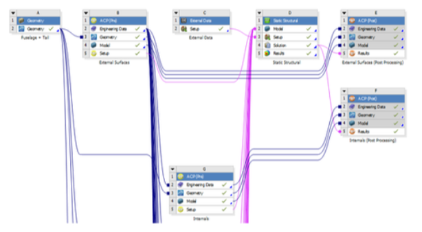
At Swift we use Ansys Workbench as our main simulations tool, which is supplemented up by other proprietary models. Some ANSYS modules used for this study included Spaceclaim for CAD, ACP for composite materials, Static Structural for FEA and Fluent for CFD. By running CFD simulations at various aircraft attitudes and speeds, e.g. VA, VC and VD, we can find the exact attitude (can be a combination of roll, pitch and yaw) and control surface deflection that causes the highest mechanical loading for a given point on the flight envelope. The Ansys post-processing software CFD-Post is then used to transfer the full pressure distribution to the FEA component.


FEA Model
Spaceclaim was used to create a full global model of the aircraft and all its structural components. This model is essentially a large assembly of surface and volume bodies. ACP-pre was then used to apply the composite ply materials, stack-ups and orientations to all the composite bodies such as frames, ribs and external surfaces. Once brought in to Static Structural, all these composite components as well as the non-composite parts, were appropriately connected using bonds and joints.
Static Structural simulations require boundary conditions to run. In this case, we needed to use Inertial Relief with a remote displacement set at the CoG to balance the accelerations produced by the applied pressure distribution and the mass distribution of the aircraft structure. Additional point masses were used to simulate the effect of pilots, engines and any other features of the aircraft that were not explicitly modelled.
By using the solution of this simulation, we could examine relative deformations, stresses within the composite laminate stack up and Von Mises stresses for the isotropic materials. These, in combination with specific composite failure criteria, were used to optimise the aircraft structure.